Converter for 4-Pin PWM connector to 2 or 3-Pin fan, Version 2
Some times you have a 4-pin regulated fan output that does not allow voltage control, but what you want to use is a 2-pin or 3-pin fan that is controlled by its operating voltage. For me, this happened when I wanted to replace the fan on my graphics card due to noise. I had a very nice 3 pin fan, but no way to control its speed from the graphics card.A search on the web was unsatisfactory. I only found rather primitive circuits and hence decided to roll my own. This is the 2nd version with a reduced compontent-count and better stability.
No warranty: This circuit comes with no warranty of any kind. If it fries your computer, burns down your house and empties you bank-account, that is not my problem.
PWM to Voltage circuit
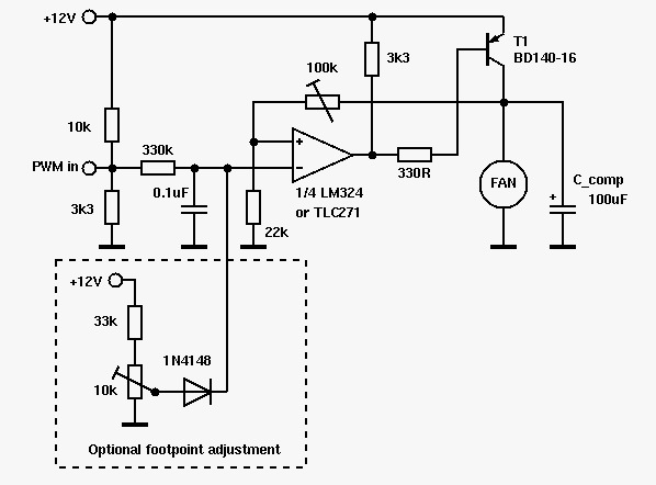
This circuit assumes the PWM output uses an open-collector/open-drain design at around 25kHz, as is standard for PWM-controlled PC fans. The voltage the open-collector PWM driver sees is about 3V, which is in line with the suggestions from the PWM signal spec. The LC low-pass filter does the conversion from PWM to voltage. A standard LM324 then drives a PNP transistor that drives the fan. The pull-up resistor at the the output of the LM324 is needed, because the LM324 cannot reach the positive voltage rail. The 330R resistor needs to be a 0.5W type, the rest is non-critical.
For the unused amplifiers, tie their output to the negative input and the positive input to GND. You could in theory also use the LM358 (dual version) or even the LM321 (single version), but at least from my supplier they are more expensive than the LM324. You could also use OpAmps like the TLC271 (slow mode).
On the bottom, there is an optional circuit for adjusting the floor-point, i.e. the minimal voltage the fan sees. Without it, at 0% PWM-on, the fan will get close to 0V. With it, it can be adjusted in the range 0V....12V. This is useful if your PWM output delivers a floor-point where your fan does not start.
Maximum Load
I recommend using a heat-sink from 0.2A fan current at 12V upwards. For the 0.15A fan I used, no heat-sink is necessary (you are welcome to add one though). Make sure the transisor has airflow, no packing it in heat-shrink tubing or the like. If you use a heat-sink, mount the transistor insulated, as it carries the positive fan voltage on its case.Maximum rated fan current with an adequate heatsink is around 0.5A at 12V. Above that the OpAmp drive strength is not large enough anymore and cooling the BD140 adequately becomes difficult. For more current, I recommend using a power P-FET like the IRF9540(N) (cheap, good general availability) as driver transistor. Cool it with a 5C/W heatsink, and you can support fans with up to a combined 3A at 12V. Note that this assumes the fans draw significantly less current at lower voltages. Normal fans do.
Do not omit the resistor at the FET-gate or you may get oscillations due to the capacitive load the FET represents.
Stability
The driver transistor provides voltage amplification and hence this is exactly the type of OpAmp circuit that may be unstable. The problem is that OpAmps are typically compensated only down to amplification 1, but with an additional amplifier in the feedback-loop, the OpAmp may be operating at amplification less than unity. The solution is to do additional compensation. As this circuit does not need to react fast, the most simple approach is to slow down the output changes. C_comp does that.In a sense, this whole circuit is a low-drop voltage regulator with a variable reference voltage. Low-drop voltage regulators need output filter capacitors for stability for similar reasons as this circuit does. The value of C_comp is pretty non-critical, a generic 100uF electrolyte capacitor is a good compromise and should work for all loads a BD140 or IRF9540 can support.
PWM signal
You can directly connect the PWM signal from the fan to the 4-pin fan connector. It is an open-collector signal and works independent of fan voltage.Adjustment
The 100k adjustable resitor in the feedback path is used to set the amplification. With the input open (corresponding to 100% PWM on), adjust it to the maximum fan speed you want to see. It is possible to adjust it higher, so that the fan will reach full speed at less PWM-"on" level, but that requires a calibration aid, see below, and replacing the lower voltage-divider resistor by something smaler, e.g. 10k.If you have the floor-point circuit, first adjust the amplification with PWM input open, and then tie the PWM input to GND and adjust the floor-point as desired.
Arduino
This circuit can also be driven direcly from an Arduino PWM-output with minimal modification. In this case, the 0.1uF capacitor should be increased to 1uF (an Arduino PWM only has around 1kHz) and the 10k resistor to 12V at the input should be removed. The Arduino can run at 5V or 3.3V.PWM Calibration Aid
The circuit below generates an open-drain PWM signal with "on"-time between 10% and 90%. It is suitable for finer adjustment of the PWM-to-voltage converter. Using a CMOS 555 timer allows for easy duty-cycle adjustment, as pin 3 has a pretty symmetric ouput voltage, different from a bipolar 555. And the discharge pin (pin 7) is perfect as open-drain output.Note that while the ICM7555 datasheet does not state any ESD immunity, the chip has upper and lower protection diodes at all pins (except pin 7, which just has a lower one, as an upper one would break the usability as open-drain output, but an open-drain output has high ESD resistance anyways) and should be pretty rugged against ESD. I assume the same is true for the other CMOS 555 variants.
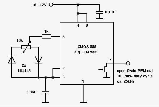
The circuit is missing the traditional filter cap on pin 5. The datasheet for the ICM7555 says it is not needed. If you do not have a 3.3nF capacitor, use a 2.2nF and 1nF one in paralell, or a 4.7nF and 10nF one in series.
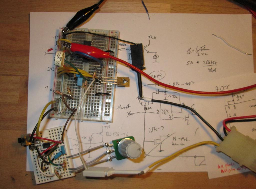
Pictures
- My messy original V1 test setup, including the PWM generator on the bottom left. The fan is to the right (not visible).
Last update: January, 2015 Arno Wagner