GPIO Startup Behaviour and how to fix it
Uppose you have some external circuit connected to the Pi, and this external circuit should only become active after some software of yours has started running. One way to do this is to dedicate one GPIO pin to this function, i.e. use it do deliver an "enable" signal which is set to inactive initially. As long as it is at its default state, disable the external circuit. Then have your software change the state to a clearly non-default value, which activates the external circuit.Warning: I also list options for interfacing to 5V logic here. While possibly safe, without the datasheet I cannot be sure. See here for a more detailled explanation
First Boot
On the Pi, the GPIOs are always configured as input after power-up or reset. Initially, both pull-up and pull-down are enabled. At least that is what I observed with mine on the first boot. Other people have also seen both being off and the signal-level floating. That is not really any better. To make matters worse, according to the limited datasheet published, the configuration with both on cannot actually be set. So Broadcom is delivering the chip with an invalid setting at least in some cases.Update: I just got my second Pi, and what is going on is actually a bit more complicated. With GPIO numbers according to elinux, a factory-fresh Pi gives this behavior:
- GPIO 4,7,8 have pull-ups on, at about 50K Ohm to 3V3.
- GPIO 28 and GPIO 29 have 10M Ohm (WTF?) pull-ups to something
like 2.9V.
With my digital Multimeter's 10M Ohm input resistance, this
gave me the 1.5V reading that kept confusing me. Apparently,
I never measured again on these pins, as this is still present
on my first Pi.
If you connect this directly to a CMOS input, you may see any voltage between 0V and 3V3, possibly even dependent on humidity... - GPIO 2, 3 have 1k8 Ohm external pull-ups to 3V3, as required for I2C.
- All others are configured with pull-down resistors of about 50K Ohm.
Even if you have sane pull-up or pull-down settings, you may have some that your connected hardware cannot tolerate, e.g. from doing other experiments. In that case, it is best if the hardware enforces the initial states via external resistors.
WARNING: The state of the pull-up and pull-down resistors is persistent over a power-cycle and can very likely only changed a limited number of times before things break permanently. See below.
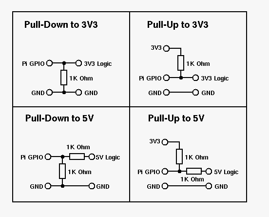
As the driving strengt of the pull-up and pull-down resistors is very limited, an external resistor of 1kOhm to GND (preferred, as a clear L signal is stable even when the psupply voltages still stabilize) or +3V3 (may be problematic as it is hard to detect reliably while 3V3 or 5V are not yet stable) can generate a clean, externally imposed initial signal. The GPIO can then be switched to output under software control and its level changed to override the resistor to signal to external logic that it can now go active.
To output data as shown below, you should set the driving strength to at least 4mA. Otherwise the signal levels may be inadequate. According to the limited datasheet, the default drive strength is 8mA, (and I found on my Pi 8mA for pins 0-27 and 16mA for pins 28-45) so no need to change anything.
And remember that the total I/O current for the GPIOs is something like 50mA, so don't use this form of external pull-up/pull-down on all pins, it may damage your hardware. Using it on one or two pins is perfectly safe though.
Also remember that GPIO 2 and 3 are different. They already have
pull-up resistors for I2C, do not use the scheme below on them.
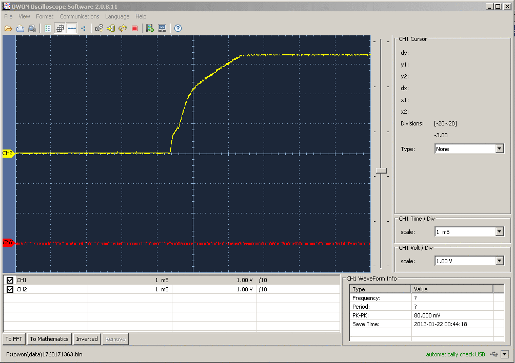
Here is what the start-up behaviour looks with 1k Ohm pull-down resistors. Red is the GPIO voltage and yellow is the 3V3 voltage from the Pi.
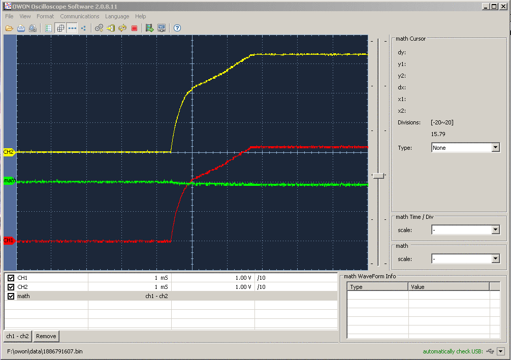
And here how it looks with an 1k Ohm resistor to 3V3. The green line is the difference, shifted for better visibility. As can be seen, the output voltage follows the 3V3 line very closely. As above red is the GPIO voltage and yellow is the 3V3 line from the Pi.
So then, problem solved. Your external hardware enforces the power-up output voltages on the GPIO pins it needs. Read on for an example of why you may want to do that in the first place.
Why all that Effort?
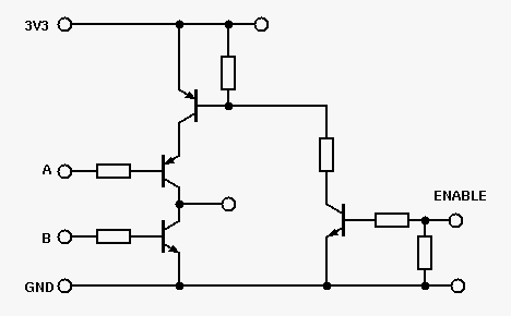
Here is an simple example on how you could disable a power-driver stage via an "ENABLE" signal that is initially L and goes to H when the driver stage should become active. The assumption here is that the two driver signals "A" and "B" may be active during power-up, shortening out the supply voltage and killing themselves and possibly the power delivery circuit. For example, if you drive A and B each with a Pi GPIO in the default delivery state (on my Pi), the 1.55V will cause both transistors to switch on! This example is somewhat simplistic and contrieved but illustrates the situation well.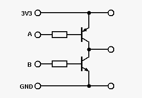
In the modified circuit below, additional transistors are used to disable the power-stage until the ENABLE pin goes high.
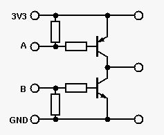
Often you do not need something this complicated and just need to ensure different GPIOs come up with different output signal levels. In my example, you could just use an external pull-up resistor for A and an external pull-down resistor for B (each 1k Ohm):
Changing pull-up/pull-down state too often?
Note: I am currently (December 2013) investigating this issue again. I may have made a measurement error. Updates as soon as I find time to find out what is really happeningWhile the GIPO pins are inputs on power-up, the pull-up/pull-down resistor states are persistent. Unfortunately, this persistence is implemented in hardware, it even shows up when there is no SD card attached.
WARNING: It looks like the state of the
pull-up/pull-down resistors is stored in some kind of EEPROM
cell. These have a limited number of overwrites before they
break permanently. It is unclear how many, due to the
unavailability of the datasheet. Typically, these cells have
between 1k and 1M writes before they start to break, but the
high figure is with a manufacturing process optimized
for these cells. In Microcontrollers, I have seen between
10k and 100k allowed write cycles.
To make maters
worse, the state of the pull-up and pull-down resistors cannot
be read back or reliably detected without external circuitry.
Recomendation: Until the missing information becomes available, I strongly recomend not changing the pull-up/pull-down resistor state more often than necessary and in particular not writing it on boot-up or when some software starts. In fact, the only safe thing I see is to disable the pull-up and pull-down resistors once manually, and then never change them again. Or to leave the broken default settings in effect, see above.